

")
Hover

Hover

Hover

Hover

Hover

Hover

Hover
")


Volkswagen T-Roc Workshop Manual (2017–2021)
$9.99
Unlock the full potential of your Volkswagen T-Roc with this official workshop manual (2017–2021). Covering everything from routine maintenance to advanced diagnostics, this PDF guide features wiring diagrams, detailed instructions, and manufacturer-approved specs. Ideal for professionals and DIY enthusiasts, it works seamlessly on all devices and is fully printable. Download instantly for expert-level repairs!
Description
Volkswagen T-Roc Workshop Manual (2017–2021) – Your Essential Repair Guide
Take complete control of maintaining and repairing your Volkswagen T-Roc with this official workshop manual. Trusted by Volkswagen service centers, this comprehensive guide covers everything from routine maintenance to intricate repairs, ensuring your T-Roc stays in perfect condition.
Key Features for the Volkswagen T-Roc Workshop Manual
- Authentic Factory Repair Manual: Used by official Volkswagen dealerships for precise repairs.
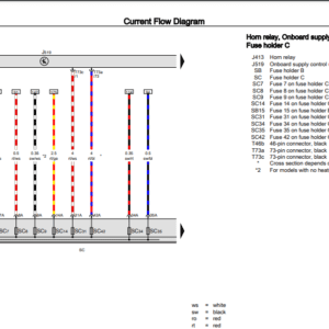
- Wiring Diagrams Included: Comprehensive diagrams for seamless electrical troubleshooting.
- Complete Technical Details: Step-by-step instructions, illustrations, and manufacturer specifications.
- Device Compatibility: Works across all devices—laptops, tablets, smartphones (Android, iOS, Windows, Linux).
- Printable: Easily print pages or chapters for on-hand use during repairs.
Applicable Models
- Make: Volkswagen
- Model: T-Roc
- Years Covered: 2017, 2018, 2019, 2020, and 2021
- Engines: V8 Petrol, TD6
- Transmission: Automatic
Table of Contents Highlights
- Transmission & Gearbox: 6-speed and 8-speed gearbox maintenance and repair.
- Engine Service: EA888 and EA211 engines, including CHZB, DKRA, DKZA, and more.
- Fuel System Repairs: Detailed procedures for DFHA, DJGA, and similar models.
- Electrical Systems: Diagnostics and wiring layout for seamless repairs.
- Routine Maintenance: Scheduled tasks to keep your T-Roc running smoothly.
- Braking System: Comprehensive repair and maintenance instructions.
- HVAC: Heating and air conditioning servicing.
Why Choose This PDF Workshop Manual?
- Eco-Friendly: No physical waste—digital format only.
- Instant Access: Download instantly after purchase.
- Searchable Format: Quickly locate specific details with the search tool.
- Expert-Level Guidance: Full illustrations, diagrams, and precise manufacturer specifications.
Perform Repairs with Confidence
From diagnosing issues to performing complex repairs, the Volkswagen T-Roc Manual is your trusted partner for keeping your vehicle in peak condition. Whether you’re an automotive professional or a hands-on owner, this manual provides the precision and details you need.
Download today and give your Volkswagen T-Roc the care it deserves!
Reviews
There are no reviews yet.